
|

|
WPI Technical Theatre Handbook: Documents | 
|
|||
|
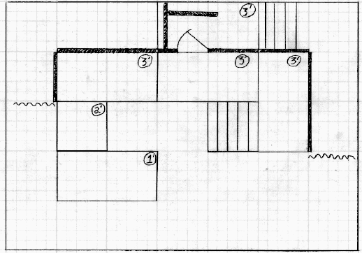
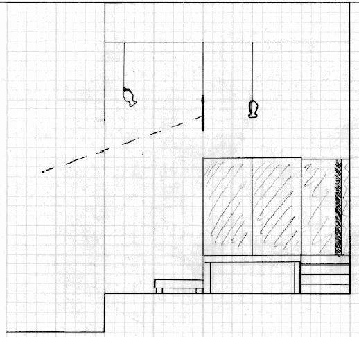
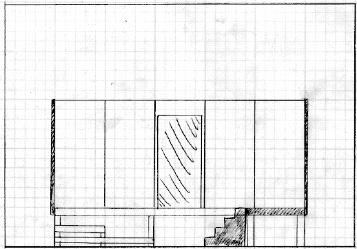
Next: Computer-Aided Design Up: Design Previous: How to Begin Contents Index DocumentsThe set designer should ideally produce a set of documents that give precise indication of the construction, positioning and look of the set. To convey this information, several drawings are used, each detailing different aspects of the set design. The designer's perspective sketch is a rough 3-dimensional picture that indicates the general feel of what the set is to look like. Producing this sketch usually requires a fair degree of artistic talent, which is why computer-generated set renderings are sometimes used to show the look and feel of a set. To determine the amount of space that a set may take up on stage, several factors must be considered. Obviously, the physical limitations of the stage must be taken into account. The height of the gridiron, width of the proscenium, and depth of the stage are the most important dimensions to consider. In addition to these limitations, sight lines must be considered. Sight lines define the extremes of the stage area that the audience can see. If a set is too big, not everyone in the audience will be able to see all of the action. In theatres that do not have permanent seating, such as Alden Hall at WPI, temporary seating is generally used. Since there is often no standard way for setting this seating up, the House Manager should be consulted so that sight lines may be determined. The ground plan is a top-down view of the stage, and shows the location of flats, platforms, etc. Also included are the locations of masking legs, fly system battens, etc. The sectional drawing is a side view of the stage, taken from the center point. Heights of battens and legs are indicated on this drawing, mainly for purposes of sightlining. Lastly, front elevations are measured drawings of each panel and piece of the set, as seen from the front. These three drawings together are generally enough information to construct the basic set. Figures 3.6, 3.7, and 3.8 show examples of these diagrams. Note that these diagrams are not USITT-standard diagrams, but it is unusual to find USITT standards used at WPI.
In some theatres, it is up to the set designer to produce what is known as the construction drawing. This diagram details construction methods and materials for each piece of the set. Often, though, the construction methods are left up to the Master Carpenter, unless something specific is necessary. This is the method most frequently used at WPI.
Next: Computer-Aided Design Up: Design Previous: How to Begin Contents Index Steve Richardson 2000-07-06 Use of information in this document implies understanding and agreement with the copyright and terms of use. Specifically, no warranty is expressed or implied regarding the accuracy of the information contained within. YOU USE THIS INFORMATION AT YOUR OWN RISK. All trademarks are property of their respective owners. You must obtain permission from the author before using the contents of The Handbook for anything other than private use. |
Table of Contents
| ||||
![[PDF]](/~prefect/images/pdficonsmall.gif) [Whole book in PDF 5.3MB]
[Whole book in PDF 5.3MB]