| |


Next: Output Assign Module
Up: Control Board
Previous: Control Board
Contents
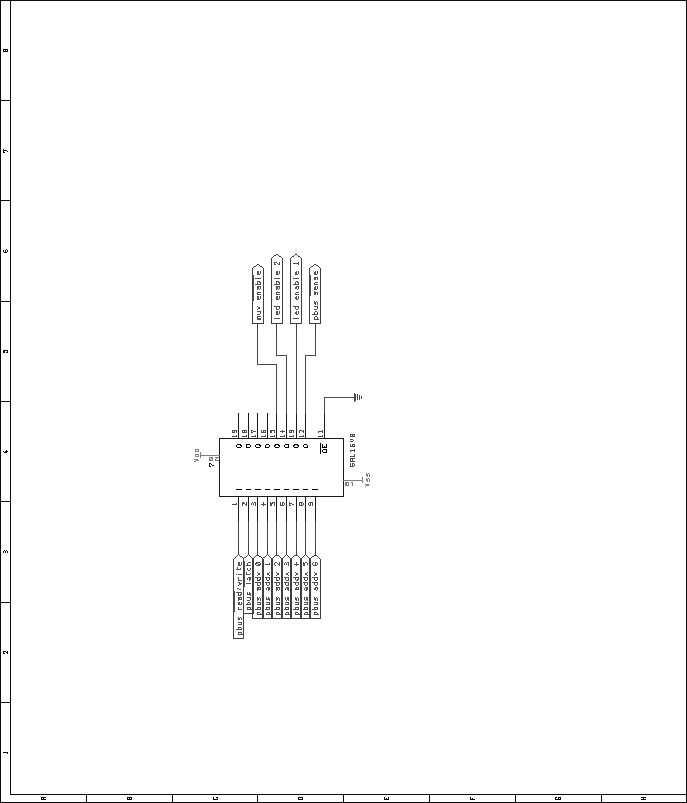
The fader module uses a standard block of Pbus interface logic. A 16V8
GAL (gate array logic) chip shall provide address decoding functionality.
Figure 41 shows the pin assignments of this piece of
programmable logic. While other means of address decoding are certainly
possible, a GAL was used to reduce chip count, and provide enhanced
functionality. The fact that GALs are completely programmable allows
any address to be decoded. Thus, different GALs with different addressing
may be used for duplicate boards in a system.
The VHDL code used to generate the GALs is included in the appendices,
on page ![[*]](crossref.png) . .
Figure 41:
Fader module, address decoding GAL pin layout.
 |
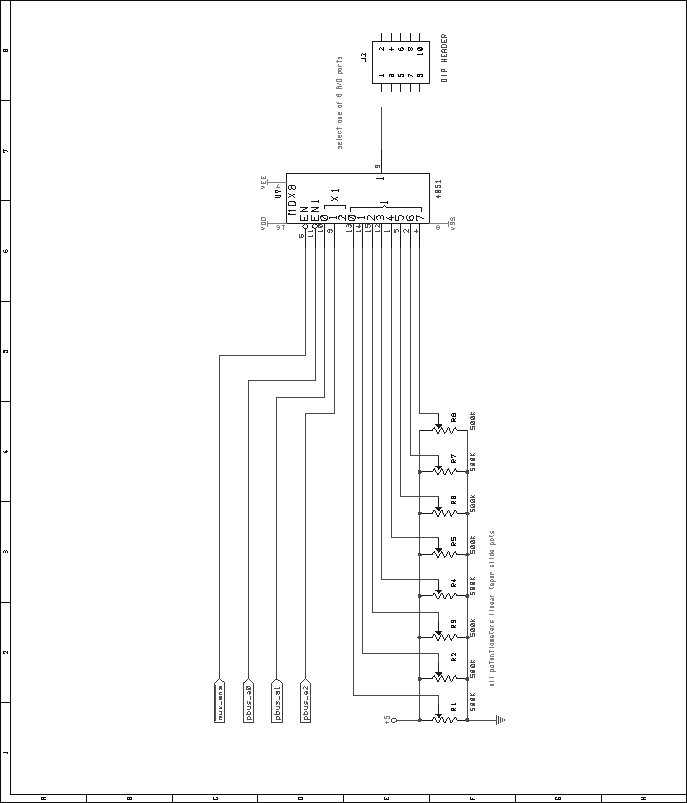
To reduce the number of A/D ports required, the eight slide potentiometers
are connected to a 4051 8-to-1 analog multiplexer. The schematic shown
in figure 42 shows how these potentiometers are connected.
A single enable line generated by the GAL enables the address lines of
the 4051.
Figure 42:
Fader module, analog multiplexer circuit for potentiometers.
 |
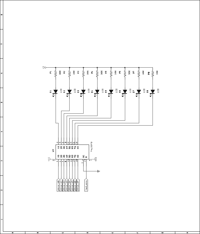
Sixteen individually addressable status LEDs are driven with a pair of
74LS373 octal latches. The LEDs are arranged such that the '373 is
sinking the current when the LED is on, thus the status of the LEDs
will appear inverted. Note that other schemes could have been used to
drive the LEDs, but the latched method reduces CPU load considerably,
as there is no refresh cycle to chew up CPU time, as in a multiplexed
design. A pair of enable lines, generated by the address decode GAL,
activate each latch. Figure 43 shows one of two of
the LED driver circuits needed for the fader module.
Figure 43:
Fader module, LED driver schematic. The module needs two of these
circuits, for a total of 16 LEDs.
 |
Next: Output Assign Module
Up: Control Board
Previous: Control Board
Contents
Steve Richardson
2000-07-06
|
Table of Contents
![[PDF]](/~prefect/images/pdficonsmall.gif) [Whole document in PDF 1.9MB]
[Whole document in PDF 1.9MB]
[more photos and information]
|