
|

|
DACS: Timing and Levels | 
|
|
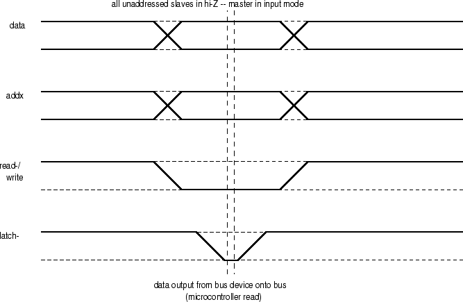
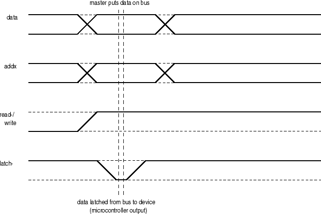
Next: Control Board I/O Map Up: Digital Control Bus Previous: Physical Specifications Contents Timing and LevelsThe Pbus is a relatively low-speed digital I/O bus. Timing is not exceptionally critical, as the speed of the bus is in the sub-1MHz range. Nevertheless, a visual reference to the bus timings is useful to fully understand the Pbus . Figure 35 depicts the timing for the Pbus master reading data from a slave device. Figure 36 shows the timing for the Pbus master writing data to a slave. Note that the control signals of the bus are level-sensitive, not edge-triggered. During the time when a particular input or output window is active, there is a transparent window between the master and the active slave(s), in the direction dictated by the direction control line.Steve Richardson 2000-07-06 |
Table of Contents
| |
![[PDF]](/~prefect/images/pdficonsmall.gif) [Whole document in PDF 1.9MB]
[Whole document in PDF 1.9MB]