| |


Next: Timing and Levels
Up: Digital Control Bus
Previous: Digital Control Bus
Contents
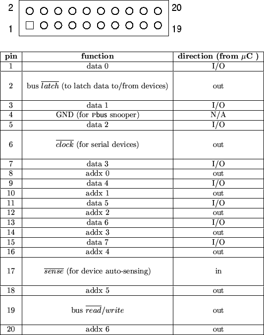
The Pbus is physically built around commonly available 20-pin DIP headers,
ribbon cable and insulation displacement connectors (IDC). The
pinouts are depicted in figure 34. Note the
presence of a single ground pin. Slaves on the Pbus shall not
use this as a ground; it is present to simplify connection of an external
bus snooper.
Figure 34:
DACS Pbus , physical description.
A standard 0.100 inch DIP header of 20 pins shall be used to connect each PC
board to the bus. The bus itself shall be carried on 20 conductor
ribbon cable, with each PC board connection made via a 20
conductor IDC. All signals are standard TTL levels.
 |
Typical  C connection to the Pbus shall be made via a few byte-wide I/O
ports, a peripheral I/O controller such as the venerable Intel
8255, or through a piece of programmable logic.
With 7 bits of address space and a byte-wide data bus, there exist 128
input and 128 output ports in this bus. I/O maps are given for the
control board and mixer unit in a later section. C connection to the Pbus shall be made via a few byte-wide I/O
ports, a peripheral I/O controller such as the venerable Intel
8255, or through a piece of programmable logic.
With 7 bits of address space and a byte-wide data bus, there exist 128
input and 128 output ports in this bus. I/O maps are given for the
control board and mixer unit in a later section.
Next: Timing and Levels
Up: Digital Control Bus
Previous: Digital Control Bus
Contents
Steve Richardson
2000-07-06
|
Table of Contents
![[PDF]](/~prefect/images/pdficonsmall.gif) [Whole document in PDF 1.9MB]
[Whole document in PDF 1.9MB]
[more photos and information]
|