
|

|
DACS: Module Overview | 
|
|
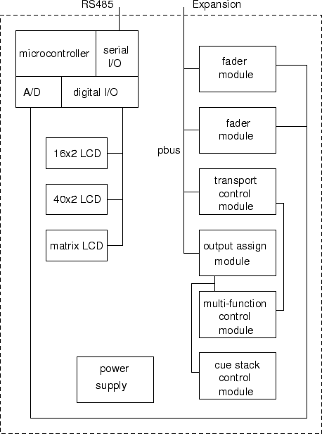
Next: Fader Module Up: Control Board Previous: System Description and Diagram Contents Module OverviewFigure 11 shows the various components of the control board, at the module level. The control board is designed in a modular fashion, such that larger models with dozens of faders, transport controls, etc. can be built. In addition, an expansion port provides the option to connect external add-ons, such as external fader boards and meter bridges. Unfortunately, there is very little module duplication possible in this piece of hardware. The obvious options were to make one large module, or use the approach presented here. This design was chosen with an eye towards expandability as well as manufacturing cost. Manufacturing one large PC board costs a significant amount of money, whereas some money is saved by the duplication of the largest board, the fader module. It can be argued that the cost of the components required to connect all of the boards together is significant, but in general it seems a wise decision from an engineering standpoint to make smaller modules that can be combined into many different forms, not to mention debugged in a more sane fashion. This technique is often employed in lighting control boards, where different sized boards are built from small, modular building blocks.Next: Fader Module Up: Control Board Previous: System Description and Diagram Contents Steve Richardson 2000-07-06 |
Table of Contents
| |
![[PDF]](/~prefect/images/pdficonsmall.gif) [Whole document in PDF 1.9MB]
[Whole document in PDF 1.9MB]