| |
![[bracket photo]](bracket_1_sm.jpg) |
![[bracket photo]](bracket_2_sm.jpg) |
![[bracket photo]](bracket_3_sm.jpg) |
![[bracket photo]](rfshield_1_sm.jpg) |
![[standoff photo]](standoff_1_sm.jpg) |
![[standoff photo]](standoff_2_sm.jpg) |
![[standoff photo]](standoff_3_sm.jpg) |
![[standoff photo]](standoff_4_sm.jpg)
![[standoff/mylar photo]](mylar_1_sm.jpg) |
Credit for the basic design of this bracket goes to Fred Maxwell, who
convinced me that the four-point mounting scheme was really a much more
sound engineering idea than the two-point. One key difference between our
methods is that I replaced the stock standoffs with nylon screws, while Fred
added spacers and used larger screws to attach to the existing heatsink
standoffs.
- Apply heat to each of the four stock heatsink mounting standoffs. Do
this using a soldering iron - preferably one that is temperature controlled.
After about 10-15 seconds of heat, the standoff should come free from the PC
board. BE CAREFUL, as it will be VERY hot. Allow it to cool and put it
someplace safe, should you ever want to re-install the original heatsink.
- Replace the four standoffs you just removed with 1.5" long 4-40 nylon
screws. Thread a nut on to each shaft and snug them to the PC board. Then
thread a second nut on each shaft, leaving about 1/2 inch or so between the
bottom nut and the top nut. Place a piece of mylar over the battery,
attached at one point to the nearest standoff (see photo). This is to
prevent the top of the battery (which is positive!) from coming in contact
with the drive casing (which is probably grounded!).
- Using the forthcoming CAD template, mark the outline and mounting holes on a piece of
0.025" aluminum sheet stock. This material can be purchased at many
hardware stores and hobby shops.
- Using a pair of tin snips, a sheet metal shear, a metal nibbler, or
whatever else you have handy, cut out the pattern from the aluminum.
Drill the mounting holes out. Use a file to remove burrs from the edges and
from the drill holes.
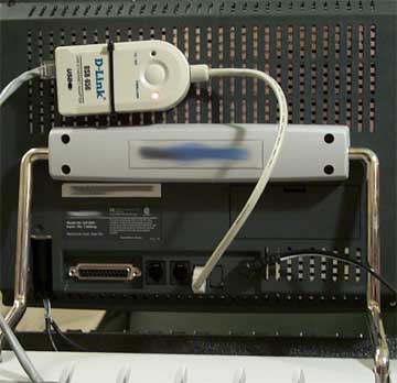
- Mount the hard disk to the bracket, check for clearances, mount the
bracket to the four nylon posts with four more 4-40 nuts. Adjust the height
of the assembly so that the HD is not contacting anything on its under-side
(which is actually the top of the HD). However, it needs to be quite close
to the components on the PCB so that the RF shield may be placed on the unit
with no clearance issues. Once the correct height has been found, use
surface clippers (such as Xcelite 170M's) or diagonal cutters to clip off
the excess nylon bolt. When the RF shield is in place, the two pockets
where the stand mounts will now be covered. You should note that the stock
heatsink has been milled to provide clearance for these holes. I'm not sure
why! Even with the aluminum plate sitting directly under the RF shield as in
the above photo, there are no clearance problems with the stand.
Note that the alternate, oft-preferred method for this type of bracket
is to not remove the PCB standoffs, but rather to use longer 2.5mm x 12mm screws and
additional standoffs to support the aluminum bracket. I chose this method
because I had a hard time locating 2.5mm screws.
|
|
|


![[bracket photo]](bracket_1.jpg)
![[bracket photo]](bracket_2.jpg)
![[bracket photo]](bracket_3.jpg)
![[bracket photo]](rfshield_1.jpg)
![[standoff photo]](standoff_1.jpg)
![[standoff photo]](standoff_2.jpg)
![[standoff photo]](standoff_3.jpg)
![[standoff photo]](standoff_4.jpg)
![[standoff/mylar photo]](mylar_1.jpg)