| |


Next: Hardware Verification
Up: Mixer Unit
Previous: Microcontroller Module (Pbus and
Contents
As specified, the mixer unit employs a linear-mode power supply. The
choice of this type of supply over a switching supply stems from noise
problems associated with switching supplies. Since one of the primary
concerns with the mixer unit is eliminating sources of noise, this
decision seemed fairly obvious.
Ideally, all components in the analog sections of the mixer would be
capable of working with a single pair of power supplies, of an
appreciable voltage (to maximize dynamic range and headroom).
Unfortunately, the ICs used in the audio mixer modules can not be run
outside of the  7VDC region. This wouldn't be a problem if it
was not desirable for the mixer to be capable of handling large audio
signals (extending up to the +24dBu range). Thus, a split supply
scheme is used, as described in earlier sections. Input and output
buffer op-amps run from 14VDC supplies, while the mixer chips
(and some op-amps) run from 7VDC supplies.
In addition to the analog circuitry present in the mixer, several
digital and hybrid ICs are used. Many of these ICs require a +5VDC
supply, thus a separate supply for this is clearly necessary. In
addition to simply requiring a different operating voltage, it makes
sense from a noise standpoint to move the digital ICs on to their own
supply. This way, any transients incurred on the supply lines
(reduced with copious amounts of bypass capacitance) do not make their
way into any audio path.
The bus combiner module presents yet another problem. The relays
chosen for the module have a very low coil resistance, on the order of
36 7VDC region. This wouldn't be a problem if it
was not desirable for the mixer to be capable of handling large audio
signals (extending up to the +24dBu range). Thus, a split supply
scheme is used, as described in earlier sections. Input and output
buffer op-amps run from 14VDC supplies, while the mixer chips
(and some op-amps) run from 7VDC supplies.
In addition to the analog circuitry present in the mixer, several
digital and hybrid ICs are used. Many of these ICs require a +5VDC
supply, thus a separate supply for this is clearly necessary. In
addition to simply requiring a different operating voltage, it makes
sense from a noise standpoint to move the digital ICs on to their own
supply. This way, any transients incurred on the supply lines
(reduced with copious amounts of bypass capacitance) do not make their
way into any audio path.
The bus combiner module presents yet another problem. The relays
chosen for the module have a very low coil resistance, on the order of
36  . With several of these running at once, a large amount of
current will be drawn from the +5VDC supply. Thus, either the primary
+5VDC supply must be capable of supplying approximately 3 amps of
current, or a secondary +5VDC supply must be employed. At the time of
this writing, a secondary high-current +5VDC supply is being planned.
The design uses standard LM317/LM337 adjustable regulators
for the audio circuitry supplies, and the venerable LM7805 for the
digital circuitry. The LM317 is a positive voltage three-terminal
``adjustable'' regulator. The LM337 is its sister part, and is a
three-terminal negative voltage regulator. These components work
by keeping a constant 1.25 volt difference between their output and
adjust terminals. Equation 1 is used for determining
component values for the output voltage. . With several of these running at once, a large amount of
current will be drawn from the +5VDC supply. Thus, either the primary
+5VDC supply must be capable of supplying approximately 3 amps of
current, or a secondary +5VDC supply must be employed. At the time of
this writing, a secondary high-current +5VDC supply is being planned.
The design uses standard LM317/LM337 adjustable regulators
for the audio circuitry supplies, and the venerable LM7805 for the
digital circuitry. The LM317 is a positive voltage three-terminal
``adjustable'' regulator. The LM337 is its sister part, and is a
three-terminal negative voltage regulator. These components work
by keeping a constant 1.25 volt difference between their output and
adjust terminals. Equation 1 is used for determining
component values for the output voltage.
 |
(1) |
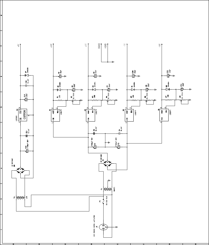
R1 and R2 refer to the resistors shown in the schematic in figure
69. Note that in the schematic, R2 is a
trimmer potentiometer. The surround capacitors, C5 and C6 in the
diagram, provide additional ripple rejection. The data sheet claims
up to 80dB of ripple rejection using this scheme. Diode D2 acts to
protect the regulator IC from capacitor discharges.
The remaining regulator circuits (utilizing U2, U3 and U4) are all
similar. The circuits utilizing U3 and U4 are negative supplies.
Each LM317/337 is capable of supplying a regulated voltage at 1.5 amps.
This is more than adequate for each supply voltage. Table
1 shows maximum calculated currents for each supply
voltage. These figures were obtained from maximum supply current
specifications from data sheets. Maximum supply current figures
were then multiplied by the number of ICs of that type used on each
power supply.
Table 1:
Maximum calculated power supply currents.  13mA maximum
supply current for NE5532 dual op-amp. Assumes full system with all
balanced input and output boards. 13mA maximum
supply current for NE5532 dual op-amp. Assumes full system with all
balanced input and output boards.  15mA maximum supply current
for SSM2163 mixer IC. Assumes full system with sixteen audio mixer
modules. 15mA maximum supply current
for SSM2163 mixer IC. Assumes full system with sixteen audio mixer
modules.
| Voltage |
Maximum Calculated Current (approx) |
| +14V |
500mA |
| -14V |
500mA |
| +7V |
500mA |
| -7V |
500mA |
|
Figure 69:
Audio mixer unit, power supplies for analog and digital
circuitry.
 |
Next: Hardware Verification
Up: Mixer Unit
Previous: Microcontroller Module (Pbus and
Contents
Steve Richardson
2000-07-06
|
Table of Contents
![[PDF]](/~prefect/images/pdficonsmall.gif) [Whole document in PDF 1.9MB]
[Whole document in PDF 1.9MB]
[more photos and information]
|