
|

|
DACS: Audio Mix Module | 
|
|
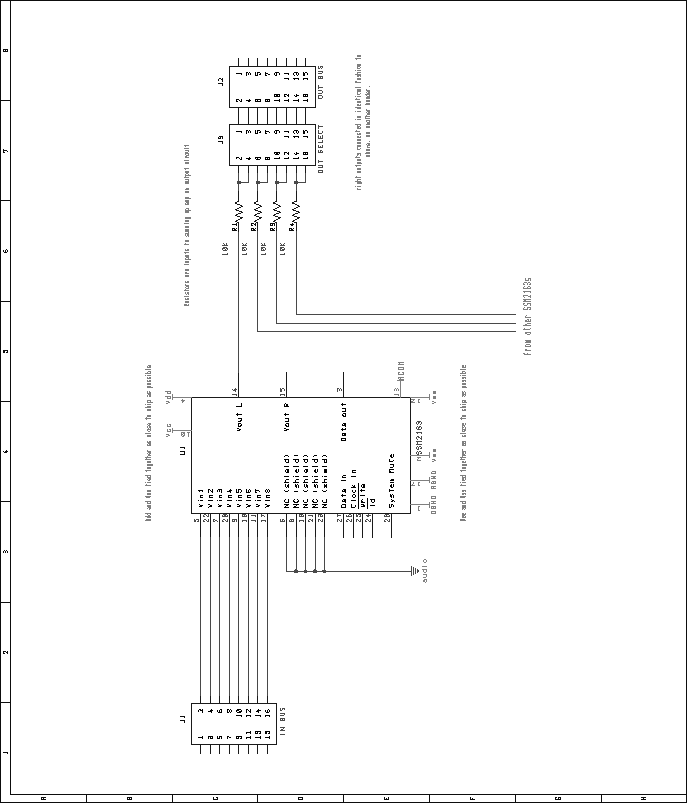
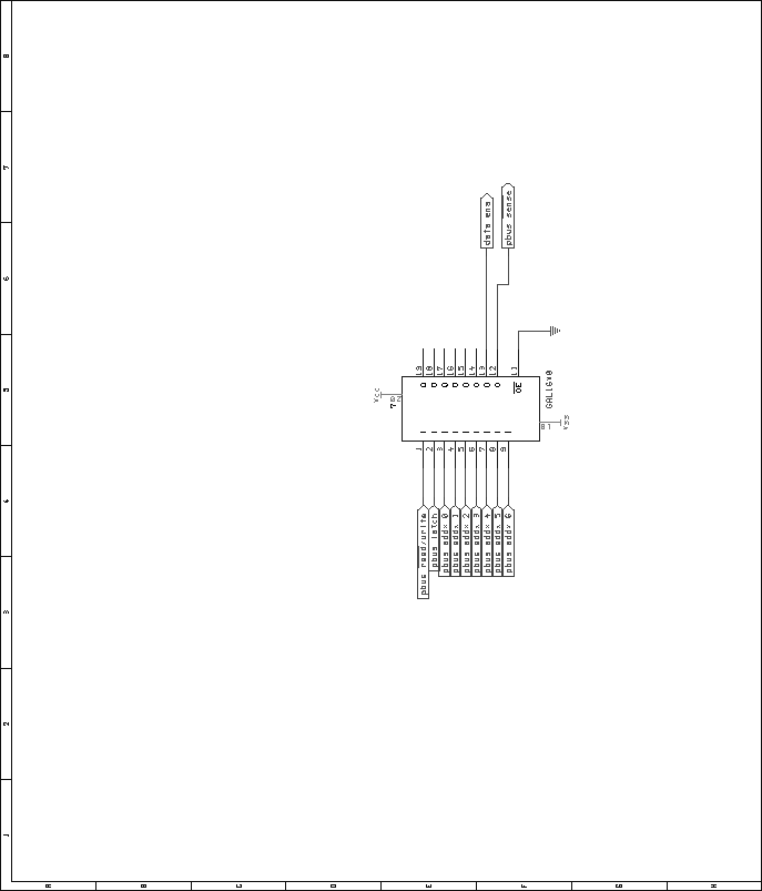
Next: Bus Combiner and Switcher Up: Mixer Unit Previous: Audio Input Module Contents Audio Mix ModuleThe mix module, the central component in the mixer unit, is actually fairly straightforward. Each module contains four of the Analog Devices SSM2163 8-to-2 attenuating mixer chips. The eight audio inputs on each of these chips are connected to the audio input buses, in a one-to-one fashion. The left output of each of the chips passes through a resistor and on to one of the output buses. The resistor is present here because of the reconfigurable mix architecture. The outputs of several chips are combined (either with the bus combiner/switcher module, or by the presence of several mix modules in the unit). The combination is accomplished through the use of a standard op-amp summing circuit, present on the input stage of the audio output module. Figure 58 shows 1/4 of the audio connections for an audio mix module. An entire module is simply this same circuit repeated four times, with each output connected to a separate output bus point. As in other DACS modules, a standard 16V8 GAL is used for address decoding. Figure 59 shows the pin assignments for the GAL. The VHDL code used to generate the GALs is included in the appendices, on page![[*]](crossref.png) .
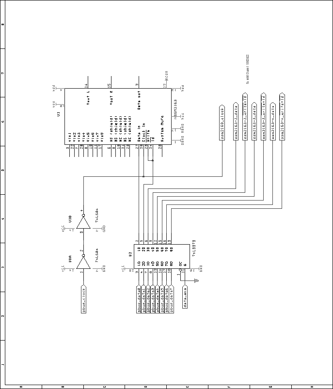
Such that all mixer chips on a module could be simultaneously, yet
individually programmed, their data and enable inputs are all
connected to a 74LS373. All clock signals are tied together, and
to the Pbus master clock signal through a pair of 74LS04 inverters
(acting as buffers in this case). This means that on any given write
cycle, four mixer chips may be programmed at once, but if the need
arises, a single mixer may be programmed without disturbing the other
chips. Figure 60 shows the digital schematic of the
mixer module. .
Such that all mixer chips on a module could be simultaneously, yet
individually programmed, their data and enable inputs are all
connected to a 74LS373. All clock signals are tied together, and
to the Pbus master clock signal through a pair of 74LS04 inverters
(acting as buffers in this case). This means that on any given write
cycle, four mixer chips may be programmed at once, but if the need
arises, a single mixer may be programmed without disturbing the other
chips. Figure 60 shows the digital schematic of the
mixer module.
Next: Bus Combiner and Switcher Up: Mixer Unit Previous: Audio Input Module Contents Steve Richardson 2000-07-06 |
Table of Contents
| |
![[PDF]](/~prefect/images/pdficonsmall.gif) [Whole document in PDF 1.9MB]
[Whole document in PDF 1.9MB]