
|

|
DACS: A/D Converter Connection | 
|
|
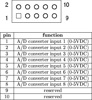
Next: Control Board A/D Map Up: Digital Control Bus Previous: Mixer Unit I/O Map Contents A/D Converter ConnectionSeveral of the modules in both the control board and the mixer unit require connection to the A/D converter present on the microcontroller modules. A generalized scheme for connecting devices to these A/D inputs is specified, such that a single ribbon cable with several inexpensive IDC connectors can be connected between all devices requiring A/D access. Each of these modules shall be equipped with a 10-pin 0.100 inch DIP header, with pinouts as shown in figure 39. A map of A/D port use is given for each piece of hardware in a later section.Steve Richardson 2000-07-06 |
Table of Contents
| |
![[PDF]](/~prefect/images/pdficonsmall.gif) [Whole document in PDF 1.9MB]
[Whole document in PDF 1.9MB]