| |


Next: Microcontroller Module
Up: Mixer Unit
Previous: Digital VU Module
Contents
As per high-level specifications, balanced and unbalanced audio output
formats are available on the mixer unit.
Balanced output modules
consist of eight XLR/Cannon style connectors and necessary driver
circuitry. Figure 24 shows the respective
functional diagram.
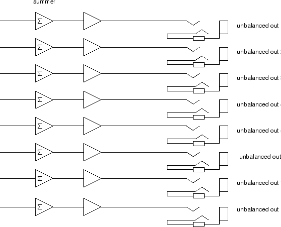
Unbalanced output modules consist of eight tip-ring-sleeve 1/4 inch
jacks, a PC board, and a metal mounting bracket. Figure
25 shows the respective functional diagram.
Figure 24:
Mixer unit, balanced audio output module diagram.
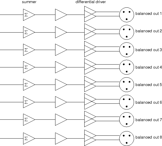 |
Figure 25:
Mixer unit, unbalanced audio output module diagram.
 |
Steve Richardson
2000-07-06
|
Table of Contents
![[PDF]](/~prefect/images/pdficonsmall.gif) [Whole document in PDF 1.9MB]
[Whole document in PDF 1.9MB]
[more photos and information]
|